Design Documentation
Satellite module models a full interactive multi-spot beam satellite network with a geostationary satellite and transparent star (bent-pipe) payload. It models DVB-RCS2 (Digital Video Broadcast - Return Channel via Satellite - 2nd generation) and DVB-S2 (Digital Video Broadcasting - Satellite - 2nd generation) specifications in return and forward link. The module has been created within European Space Agency ARTES 5.1 AO6947 project “Development of an Open-Source, Modular and Flexible Satellite Network Simulator”.
Model Description
The source code for the satellite module lives in the directory contrib/satellite.
Design
As a reference system scenario, a single multi spot-beam satellite at geostationary orbit at about 35786 km altitude is considered. The system coverage is Europe using a single satellite located at 33 degrees East using Ka-band frequency (from 26.5 to 40.0 GHz) on the feeder and user links. The user link coverage consists of 72 spot-beams and the user beams are served by 5 gateways. This is illustrated by gain patterns in Antenna gain pattern.
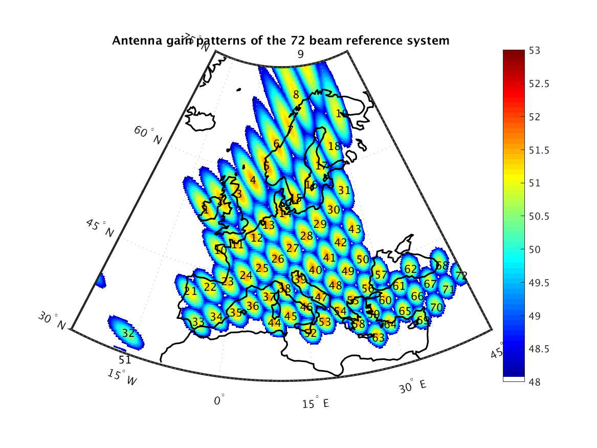
Antenna gain pattern
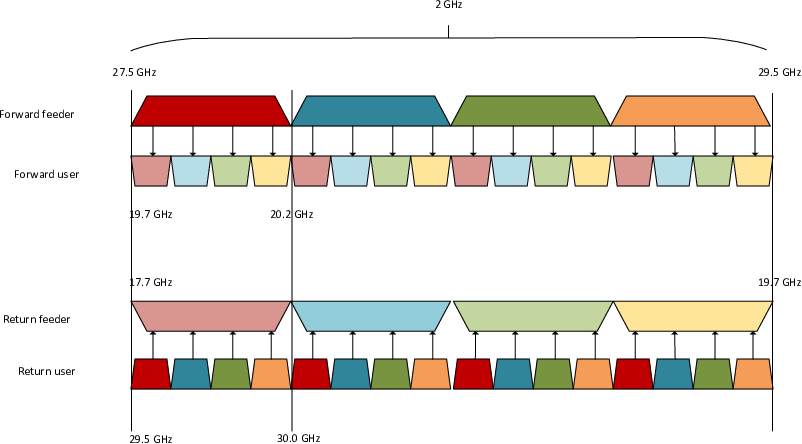
Satellite frequency plan
The system allocates 2 GHz to the feeder link: from 27.5 GHz to 29.5 GHz to uplink and from 17.7 GHz to 19.7 GHz downlink, which can be seen from Satellite frequency plan. Full frequency re-use (reuse 1) is assumed in the feeder link, which means that each GW uses the same 2 GHz band on the feeder uplink; as well as in feeder downlink.
The system allocates 500 MHz to the user link: from 29.5 GHz to 30 GHz to uplink and from 19.7 GHz to 20.2 GHz to downlink. The 500 MHz user band is divided into four 125 MHz bands (i.e. four color re-use): The user link frequency reuse pattern is presented in Dominance map of 72 beam reference system with user frequency IDs. Each spot-beam is allocated a 125 MHz band on the user uplink, and another 125 MHz band on the user downlink. Each GW can support an aggregate traffic to/from 16 beams (2 GHz / 125 MHz = 16). Thus, each GW is mapped to 16 beams. Since, the system comprises of 72 spot-beams in total, five GWs are needed to support them.
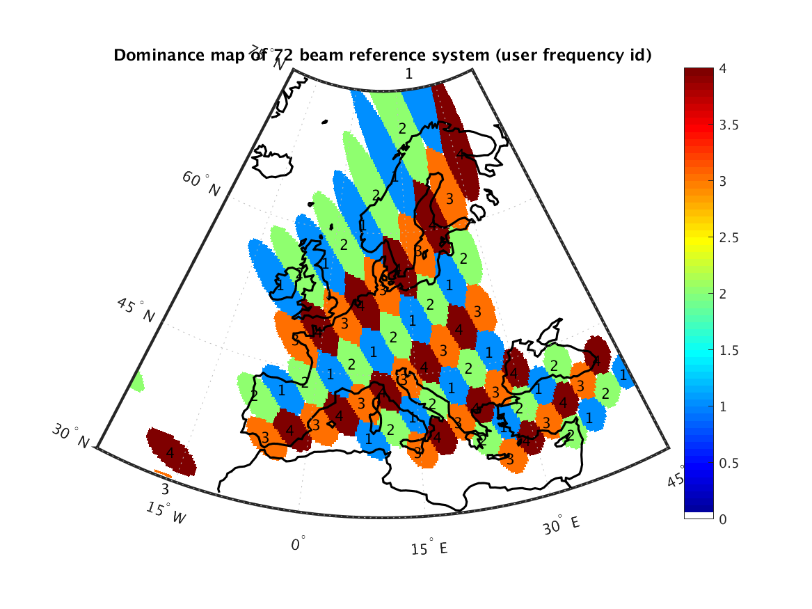
Dominance map of 72 beam reference system with user frequency IDs
Satellite module is designed to be modular and flexible so that it can be used to simulate different interactive transparent geostationary (GEO) satellite networks with minimal source code modifications. ETSI DVB-S2 and DVB-RCS2 specifications are adopted as communication standards on the forward and the return links.
Nearly every aspect of the satellite module functionality is highly configurable via numerous attributes.
The attributes can be set via input XML files, by hard-coding them into scripts
or by passing them as command line arguments in NS-3 style. For simpler configuration, there is a helper class
(SimulationHelper) which offers customization of attributes in groups by using simple function calls in a
simulation script.
Frame configuration
Return link uses a Multi-Frequency Time Division Multiple Access (MF-TDMA) which is composed of superframe sequences, superframes, frames, time slots and Bandwidth Time Units (BTUs) [dvb12-p2]. The used frame structures are dynamically configured by the Network Control Center (NCC) by using Superframe Composition Table (SCT), Frame Composition Table version 2 (FCT2) and Broadcast Composition Table (BCT). The satellite module does not explicitly model SCT, FCT and BCT, but the frame configurations may be changed by parametrization. An example of the frame structures is presented in section 5.2.3. of DVB-RCS2 guidelines [dvb12]. However, NCC models Terminal Burst Time Plan v2 (TBTPv2) and thus is capable of configuring the time slots dynamically for each superframe (e.g. start times, durations, waveforms).
Forward link is using DVB-S2 Time Division Multiplexing (TDM) structure which is described in [dvb05] Section 5. The forward feeder link 2 GHz bandwidth is divided into 16 125 MHz carriers, where each carrier is statically mapped to a user link frequency color of 125 MHz for a certain beam. Note, that only one carrier per beam is supported.
Architecture
Satellite module architecture consists of models for User Terminal (UT),
Satellite (SAT), Gateway (GW), Network Control Center (NCC), terrestrial nodes
(end users) and their interaction. In general, all satellite nodes require a
new implementation of a NetDevice (SatNetDevice), which is inherited from
NetDevice class. SatNetDevice implements Logical Link Control (LLC),
Medium Access Control (MAC) and Physical (PHY) classes specific for each node.
In addition, a new implementation of the Channel class (SatChannel) is needed
for it to support satellite system received signal power calculations.
In terrestrial link, the used access technology (behind UTs or GWs) may be anything supported by NS-3, e.g. point-to-point, CSMA, WiFi. Current helper structures assume CSMA. NCC is modeled as a shared module with all GW nodes.
Satellite module implements both spherical and geodetic coordinate systems (WGS80 and GRS84) (latitude, longitude, altitude) in addition to the default Cartesian coordinate system. New coordinate system is needed for satellite domain nodes (UT, GEO satellite and GW).
The general architecture of satellite model is presented in General end-to-end architecture
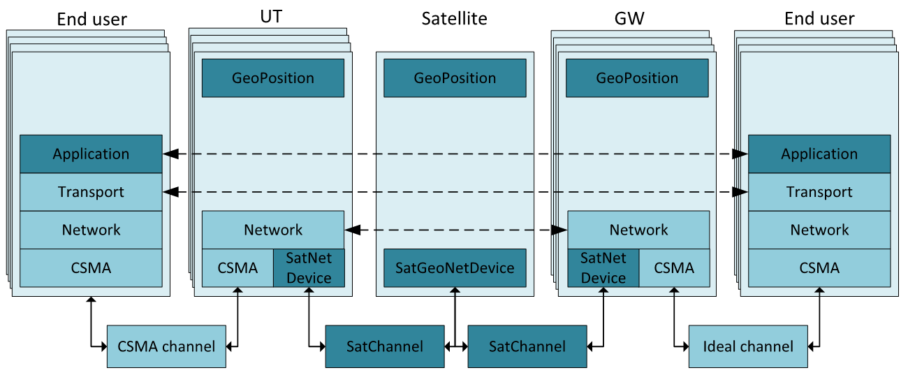
General end-to-end architecture
User terminal
In the UT DVB-RCS2 based burst transmission logic and DVB-S2 based BB frame reception logic has been implemented. Incoming IP packets are buffered to LLC layer, which implements a Return Link Encapsulation (RLE) and fragmentation/packing functionality for the return link time slots. Request Manager class is observing the queues and requesting resources from the Network Control Center (NCC) with Capacity Request (CR) messages with certain Capacity Category (CC) from NCC; i.e. Rate-Based Dynamic Capacity (RBDC) and Volume-Based Dynamic Capacity (VBDC). MAC layer implements the received TBTP processing and time slot scheduling and PHY layer actual physical transmission and reception of the packet into the channel. UT structure is presented in User terminal structure.
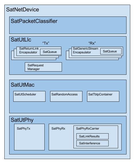
User terminal structure
Geostationary satellite
The satellite module supports currently transparent (”bent-pipe”) payload, where user and feeder links are directly mapped to each other. Satellite only amplifies the signal without any packet processing. Note, that the GEO satellite calculates also SINR, because the two phase SINR calculation has been adopted. SINR is calculated separately for user and feeder links and combined by a composite SINR equation at the final receiver [link05]. Satellite structure is presented in Geostationary satellite structure.
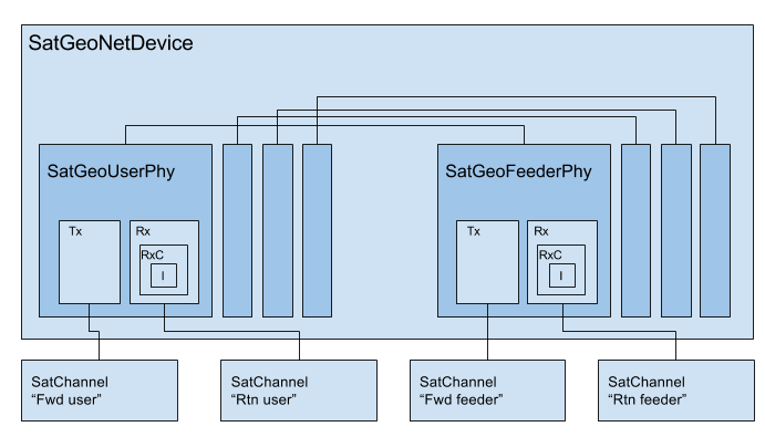
Geostationary satellite structure
Gateway
In the GW DVB-S2 based transmission logic and DVB-RCS2 based reception logic has been implemented.
Architecture of the SatNetDevice of GW is in general level quite similar to UT architecture. However,
a major difference is that GW has as many SatNetDevices as there are spot-beams served by the GW,
thus one SatNetDevice is serving all the UTs within one spot-beam. The GW’s LLC layer has one Generic
Stream Encapsulator (GSE) entity per attached UT. DVB-S2 transmitter is constantly transmitting Baseband
Frames (BBFrames), where each BBFrame holds higher layer packets with only one MODCOD. The length
of a BBFrame may be either 16200 or 64800 coded bits, thus the duration to transmit a BBFrame varies
based on MODCOD. If the GW does not have any data to transmit, it is generating dummy frames.
Gateway structure is presented in Gateway structure.
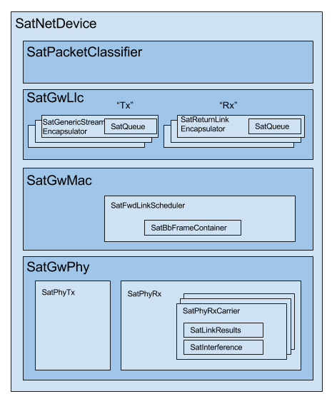
Gateway structure
Network control center
Network Control Centre (NCC) is responsible of return link resource allocations, i.e. admission control, packet scheduling, and Adaptive Coding and Modulation (ACM).
Satellite module implements one global NCC, which has completely separate scheduler (SatBeamScheduler) for each
spot-beam. To avoid the implementation of the communication protocol between GWs and NCC, the NCC has been attached to each
GW and SatNetDevice with NS-3 callbacks. This allows on one hand an ideal communication channel between
NCC and GW, and on the other hand is easily changeable to a real protocol later.
Channel
The satellite module channel implementation (SatChannel) maps into a frequency color (bandwidth).
The main purpose of a channel is to be able to pass packets within a one frequency band to all
receivers sharing the same bandwidth. In other words, all the co-channel beams are sharing the
same channel, and beams in different frequency bands are fully separated to different channel
instances.
In user link, there are a total of four channel instances (SatChannel) per direction, each
representing one 125 MHz bandwidth. In the used reference system, there are a total of
72 / 4 = 18 spot-beams sharing the same user link channel. Thus, UTs within the 18 spot-beams
sharing the same channel shall be able to interfere each other. In feeder link, there
are a total of 16 channel instances per direction (2 GHz / 0.125 GHz), each representing one
125 MHz bandwidth. All GWs are sharing the same frequency band, thus there may
be a maximum of 5 GWs sharing the same channel instance.
In figure Satellite channel structure with 16 beams, channel modeling of a 16-beam subset of the full 72-beam scenario is illustrated.
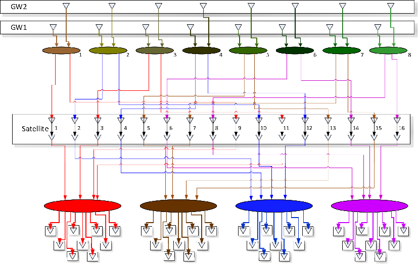
Satellite channel structure with 16 beams
Random access
There are three supported random access modes: Slotted ALOHA [dvb12-p2], Contention Resolution Diversity Slotted ALOHA (CRDSA) [aloha07], and Multi-Replica Decoding using Correlation based Localisation (MARSALA) [marsala].
Slotted ALOHA is utilized only for control messages due to its small payload capabilities. Capacity Request (CR) and ARQ ACK control messages are implemented to the satellite module, which may be transmitted through slotted ALOHA.
CRDSA algorithms are based on [dvb12-p2] and [aloha07]. DVB-RCS2 guidelines define six use cases for CRDSA: RA cold start, RA-DAMA top-up, RA-DAMA back-up, RA IP queue, RA capacity requests and RA for SCADA. In addition to “RA capacity requests”, the satellite module supports “RA cold start” use case to improve the throughput and reduce the packet delays in case where UT does not have any DA resources available.
MARSALA algorithm is based on [marsala] and aims at improving CRDSA when its SIC cycle finishes.
Return link packet scheduling
Return link packet scheduler functionality is implemented into one global Network Control Center (NCC). NCC holds independent schedulers for each spot-beam, which do not have any interaction with each other. Return link scheduler may work in three different time slot configuration modes 0-2.
Conf-0 – Scheduler is configured with a pre-defined time slot structure with a static waveform (i.e. burst length and MODCOD).
Conf-1 – Scheduler is configured with a pre-defined time slot structure with a static burst length, but the MODCOD may change between time slots/UTs.
Conf-2 – Scheduler generates time slots on-the-fly depending on UT requests, channel conditions and load. Each time slot may be using whatever waveform.
Satellite module supports waveforms 3-22, thus MODCODs ranging from QPSK 1/3 to 16QAM 5/6 with two different burst lengths (536 and 1616 symbols) [dvb12-p2]. The rest of the waveforms are not supported due to non-existing link results. GW is measuring the RTN link C/No from each received time slot, adds measurement error and forwards the report to NCC. NCC selects a MODCOD for each UT which provides the best spectral efficiency while still guaranteeing an agreed error rate.
The RTN link scheduling process for one individual beam scheduler consists of six consecutive phases [ICSSC16]:
SatDamaEntry/CR update – Process the received Capacity Requests (CR) within the previous superframe.
Preliminary resource allocation – Pre-allocate a set of soft-symbols for each UT based on configured CRA, dynamic request type (RBDC, VBDC) and value, CNo conditions and frame configurations and load.
Time slot generation – generate the time slots for each frame based on the pre-allocated soft-symbols for each UT and RC index. Fill in the TBTP on-the-fly.
SatDamaEntry update – Update the allocated VBDC bytes for each UT context
TBTP signaling – Send the TBTP message to the proper GW protocol stack handling the resources for this specific spot-beam.
Schedule next scheduling time for the next SF.
Demand assignment multiple access (DAMA)
Demand assignment multiple access (DAMA) evaluation is implemented within request manager [ICSSC16]. The DAMA algorithms are based on [dama13]. Request manager is configured through lower layer service configuration, where the DAMA configuration may be configured separately for each RC index. Satellite module supports CRA, RBDC, and VBDC capacity allocation categories.
RM evaluates periodically or on-a-need-basis the need to send a capacity request for a certain RC index. It observes the UT packet queues for incoming rates and received DA resource from TBTPs. CR is modeled as a real signaling message with transmission error probability.
UT scheduler
UT schedules the transmission opportunities (time slots) to upper layer based on the received TBTP messages from the Network Control Center (NCC). UT scheduler primarily obeys the RC indices within TBTP, but in case there are no packets available in the certain RLE encapsulator/queue for a given RC index, UT scheduler has a freedom of selecting which RC index to serve.
FWD link scheduler
FWD link scheduler builds periodically a number of BB frames and fills them with GSE packets from LLC in priority order. BB frames will be allocated an optimal MODCOD based on UT specific CNo reports. After a scheduling round, scheduler tries to optimize the BB frames by down-converting the ModCod on a need basis to minimize the amount of BB frames.
ARQ
ARQ is not a part of DVB-RCS2 specifications. However, for research objectives, selective repeats ARQ was implemented to the satellite module. ARQ works at the LLC level and with GSE (FWD link) or RLE (RTN link) packets.
Mobility and Handover
Two mobility models are implemented for UTs: a static one and one based on trace files of successive positions. For moving UTs, intermediate positions are computed as needed by use of a linear interpolation over the two closest positions in the file. Once the UT reaches the position described at the end of the file, it stays static until the end of the simulation.
A handover module has been developped that can be attached to any UT. When this handover module exist on a UT, it will monitor the carriers power around it. When the carrier it is locked to has a power that drop below a defined threshold, it will send a message asking the NCC the authorization to perform a handover to another, given, carrier/beam.
Architecture references
[dama13] B. de la Cuesta, L. Albiol, J. M. Aguiar, C. Baladrón, B. Carro, and A. Sánhez-Esguevillas, Innovative DAMA algorithm for multimedia DVB-RCS system”, EURASIP Journal on Wireless Communications and Networking, 2013.
[dvb05] Digital Video Broadcasting (DVB); Second generation framing structure, channel coding and modulation systems for Broadcasting, Interactive Services, News Gathering and other broadband satellite applications (DVB-S2), 2005.
[dvb12] Digital Video Broadcasting (DVB); Second Generation DVB Interactive Satellite System (DVB-RCS2); Guidelines for Implementation and Use of LLS, 2012.
[dvb12-p2] Digital Video Broadcasting (DVB); Second Generation DVB Interactive Satellite System (DVB-RCS2); Part 2: Lower Layers for Satellite standard, 2012.
[aloha07] E. Casini, R. De Gaudenzi, O. del Rio Herrero, “Contention Resolution Diversity Slotted ALOHA (CRDSA): An Enhanced Random Access Schemefor Satellite Access Packet Networks”, IEEE Transactions on Wireless Communications, Vol. 6, Issue 4, pp. 1408 -1419, April 2007.
[link05] K. Brueninghaus, D. Astely, T. Salzer, S. Visuri, A. Alexiou, S. Karger, G.-A. Seraji, “Link Performance Models for System Level Simulations of Broadband Radio Access Systems” IEEE International Symposium on Personal, Indoor and Mobile Radio Communications, 2005.
[marsala] K. Zidane, “Improving Synchronous Random Access Schemes for Satellite Communications” PhD Thesis, Université de Toulouse, ISAE, 2016
Scope and Limitations
Satellite module models a full interactive multi-spot beam satellite network with a geostationary satellite and transparent star (bent-pipe) payload. The reference satellite system consists of 72 spot-beams with an European coverage, 5 gateways and Ka-band frequencies. However, the system is quite flexible and other satellite systems may be configured by means of NS-3 attribute system and satellite module specific input files.
Limitations:
Configured reference system (Ka-band over Europe, 5 GWs, frequency configuration)
Only one geostationary satellite; no LEO/MEO support
No regenerative payload at the satellite
Satellite module uses currently only IPv4, thus IPv6 is not supported by the satellite helpers.
Only one superframe sequence
Same superframe configuration for all beams
Only one subcarrier per spot-beam in FWD link
References
[SIMUtools14] Jani Puttonen, Sami Rantanen, Frans Laakso, Janne Kurjenniemi, Kari Aho, Guray Acar, “Satellite Model for Network Simulator 3”, 7th International ICST Conference on Simulation Tools and Techniques (SIMUtools), Lisbon, Portugal, March 2014.
[WNS3-14] Jani Puttonen, Sami Rantanen, Frans Laakso, Janne Kurjenniemi, Kari Aho, Guray Acar, “Satellite Module for Network Simulator 3”, The Workshop on NS-3 (WNS3), Atlanta, USA, May 2014.
[AIAA14] Jani Puttonen, Sami Rantanen, Frans Laakso, Janne Kurjenniemi, Kari Aho, “A Packet Level Simulator for Future Satellite Communications Research”, AIAA Space 2014, San Diego, USA, August 2014.
[KaConf14] Vesa Hytönen, Budiarto Herman, Jani Puttonen, Sami Rantanen, Janne Kurjenniemi, “Satellite Network Emulation with Network Simulator 3”, Ka and Broadband Communications, Navigation and Earth Observation Conference (KaConf), Salerno/Vietri, Italy, October 2014.
[SESP15] Jani Puttonen, Sami Rantanen, Frans Laakso, Janne Kurjenniemi, “Satellite Network Simulator 3”, Workshop on Simulation for European Space Programmes (SESP), Noordwijk, Netherlands, March 2015.
[ICSSC16] Jani Puttonen, Lauri Sormunen, Janne Kurjenniemi, “Radio Resource Management in DVB-RCS2 Satellite Systems”, The 34th AIAA International Communications Satellite Systems Conference (ICSSC), Cleveland, Ohio, October 17 - 20, 2016.